Overview
This article presents the ability of Teiid Designer to provide a federated view of two independent data sources. Specifically, it outlines taking an XML file and a text file, creating source models from them and fusing them together in a single union view model.
Requirements
- JBoss 5.1 with a Teiid 7.6+ installation.
- JBoss Developer Studio with Teiid Designer 7.7.1 is recommended as this will align with the instruction steps and the screenshots.
- The teiid instance is recommended to be installed on the same machine as the project models being developed. However, it is possible to use a remote instance but it will be necessary to copy the source data files onto the remote machine once the models have been deployed.
Preparing the Data
The data sources to be fused consist of the following:
* [plain text file|^parts.txt.zip] (the attachment should be extracted from its surrounding zip file)
* [XML file|^parts.xml]
The files should be copied to a location where both are accessible by the Teiid installation, eg. /usr/share/teiid. Should the teiid installation be located on another host then the files should also be copied to the same location on that host as well since the final deployed VDB does not carry the data with it.
Creating the Project
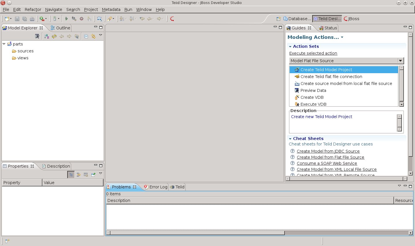
Open the Teiid Designer perspective in JBoss Developer Studio.
- In the Guides View, under Action Sets, select Model Flat File Source and double-click Create Teiid Model Project.
- Enter the project name as parts and choose a location for the project.
- Click Next> and if the Project References page is displayed, click Next> again (No projects need referencing).
- In the Model Project Options page, only leave selected the source and views folders then click Finish.
Create a Flat File Connection
A connection to the flat file's directory is established before creating a source model.
- In the Guides View, double-click Create Teiid flat file connection.
- In the wizard, give the connection a sensible name such as Parts Flat File Connection and click Next>.
- On the Define Folder or a File URI page, choose Select home folder and browse to the location of the parts text file, downloaded in the Preparing the Data section.
- Ensure the Use first line as column name indicator option is checked and click Finish.
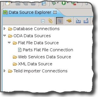
The new connection is displayed in the Data Source Explorer View accessible from the Database Development perspective.
Create the Flat File Source Model
Using the connection, it is simple to create a source model that links to the plain text file.
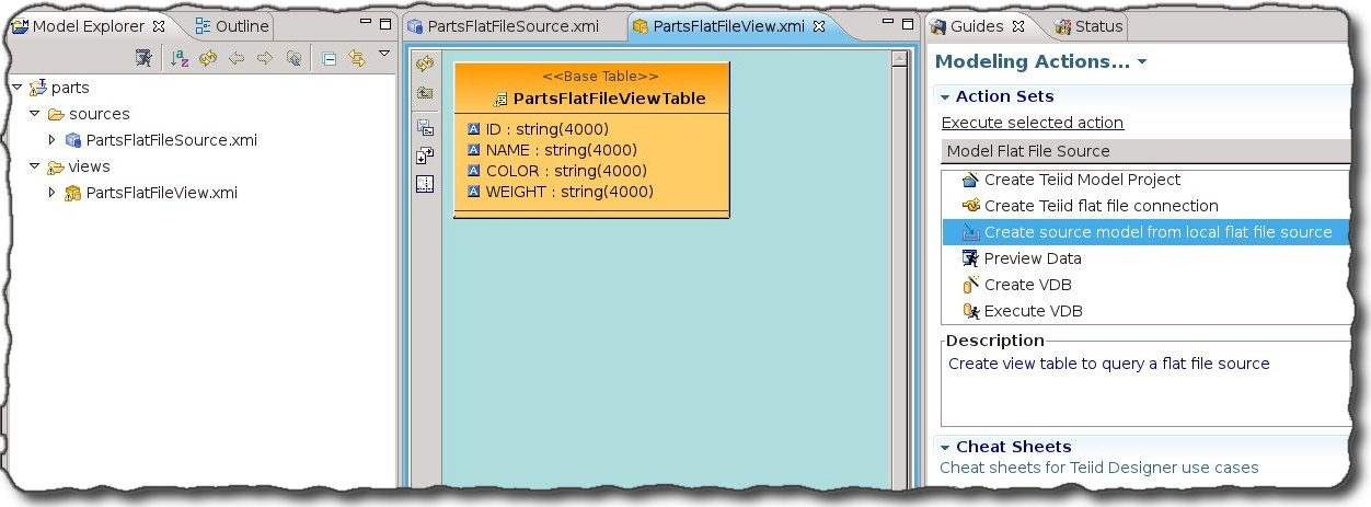
- In the Teiid Designer Perspective, from the Guides View, double-click Create source model from local flat file source.
- In the newly displayed import wizard, the created flat file connection should already be selected as the Data File Source. Select the checkbox next to parts.txt.
- Set the location of the model to be parts/sources, provide a name for the new source model such as PartsFlatFileSource and click Next>.
- The next two pages provide specific options for tailoring the model to the file's format. For the purpose of this example, it is unnecessary to change the defaults so click Next> until the View Model Definition page is displayed.
- On the View Model Definition page, set the location of the model to be parts/views, enter the name for the view model as PartsFlatFileView, its table name as PartsFlatFileViewTable and click Finish.
This completes the import of the text file as a data source. The created view model can be previewed and deployed to a VDB but this is only provides one data source. More work is required for federating data sources!
Create an XML File Connection
A similar import procedure is required for the XML data source so first an XML file connection is required.
- In the Guides View, select Model Local XML File Source.
- From the new list of actions, double-click on Create Teiid Local XML Connection.
- In the displayed wizard, give the connection the name of Parts XML File Connection and click Next>.
- On the XML Local File Connection Properties page, browse to the location of the parts text file, downloaded in the Preparing the Data section and click Finish.
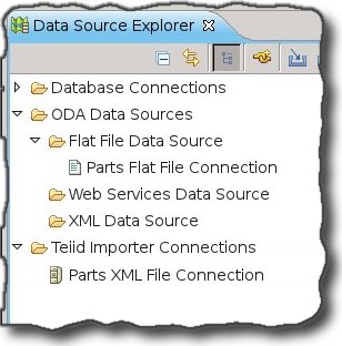
The new connection is displayed in the Data Source Explorer View accessible from the Database Development perspective.
Create the XML File Source Model
Using the connection, create the source model pointing to the xml file.
- In the Teiid Designer Perspective, from the Guides View, double-click Create source model from XML file source.
- In the newly displayed import wizard, ensure that XML file on local file system is selected and click Next>.
- In the XML Data File Source Selection page, the created XML connection should already be selected as the Data File Source. Select the checkbox next to parts.xml.
- Set the location of the model to be parts/sources, provide a name for the new source model such as PartsXMLSource and click Next>.
The newly displayed page, XML Data File Import Options, allows the creation of the data columns. Attributes and elements can be selected from the tree on the left and added to the table. Expand the tree and add four columns to the table, ie. id, name, color and weight.
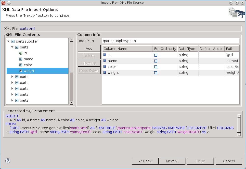
It is important to change the Root Path to /partssupplier/parts. Failure to do so will result in a teiid multi-valued attribute exception when the VDB is eventually deployed!
- On the View Model Definition page, set the location of the model to be parts/views, enter the name for the view model as PartsXMLView, its table name as PartsXMLViewTable and click Finish.


The parts project now contains two independent sets of source and view models.
Create a Union View Model
To accomplish this task, a helpful cheat sheet is provided that steps through the creation of this union view model.
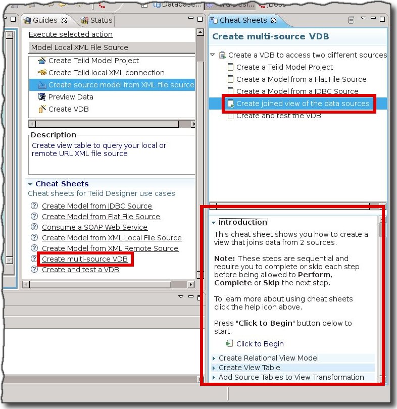
Thus, the following steps are in accordance with the cheat sheet but tailored to the text and xml models.
Create Relational View Model
- Right-click on the views folder, in the parts project, and select New > Teiid Metadata Model to open the New Model Wizard.
- In the New Model Wizard, enter the following and click Finish.
- Location: parts/views
- Model Name: PartsUnionView
- Model Class: Relational
- Model Type: View Model
- Note: No model builder is required to be selected.
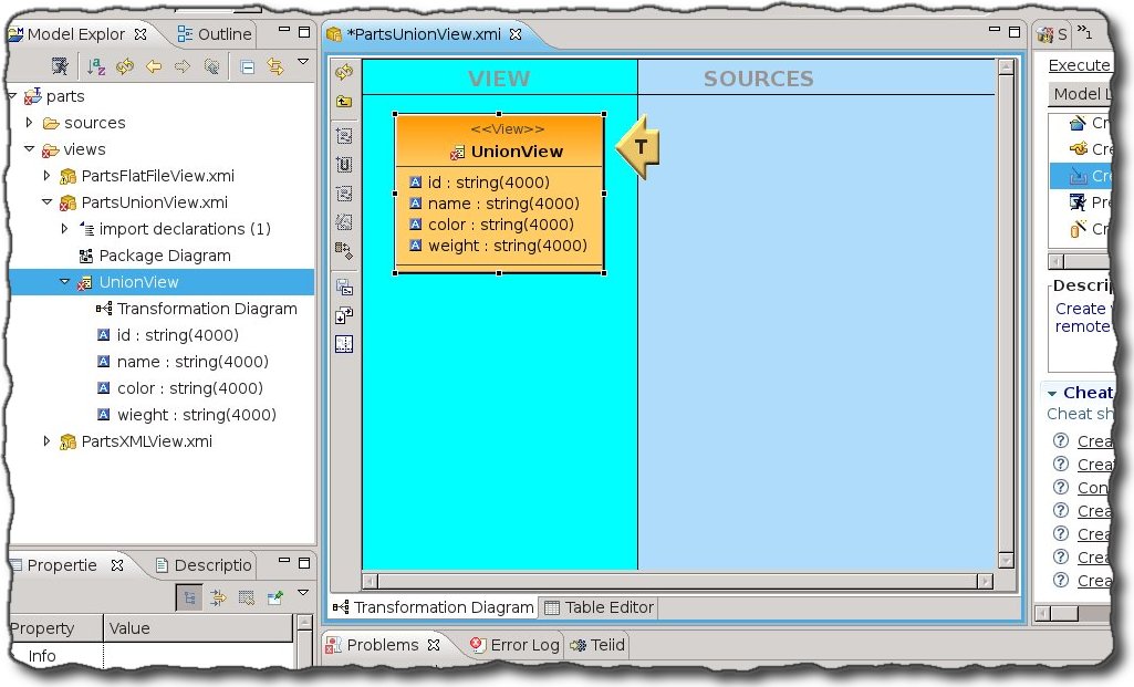
This should create a blank PartsUnionView Model Editor.
Create View Table
- In the blank PartsUnionView Model Editor, right-click and select New Child > View.
- A new View node is added to the editor with the name highlighted. Change the name to UnionView.
- This View requires columns to match those in the other views. This procedure should be done four times for each of the following columns. Select the View node, right-click and select New Child > Column and change its names accordingly.
- id
- name
- color
- weight
- For each column, right-click on it and select Modelling > Set Datatype to change its datatype to string and a length of 4000.
Add Source Tables to View Transformation
The view is now ready to be linked to the text and xml source models. This is achieved by opening the Transformation Diagram for the PartUnionView model.
In the Model Explorer View, expand the PartUnionView node and double-click the UnionView. The transformation diagram editor should be opened.
- Expand both the PartsFlatFileView.xmi and the PartsXMLView.xmi in the Model Explorer. This will display their transformation diagrams, respectively PartsFlatFileViewTable and PartsXMLViewTable.
In the Model Explorer, selecting the PartsFlatFileViewTable and PartsXMLViewTable enables the Add Union Transformation Source(s) button
 on the diagram toolbar. Click this button to add the two views as sources for the UnionView.
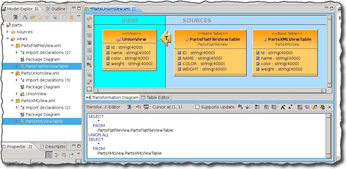
- Click the Save/Validate
 button to ensure the transformation SQL is correct.
 - Click the Save All button on the main toolbar to ensure that all models have been saved.


Test the New Model
The Preview  button in the Transformation Editor can be used for instant testing of the view. However, for a more comprehensive test a VDB can be created and executed allowing different SQL queries to be run against the views.
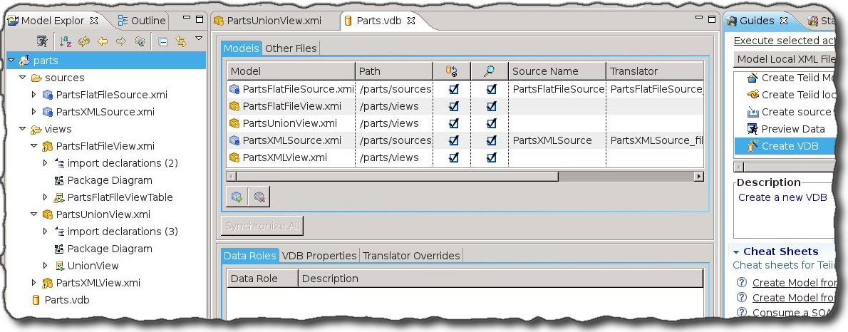
- In the Guides View, double-click Create VDB.
- In the New VDB wizard, set the Folder to be parts and the name of the vdb Parts.
- Use the Add button to select the PartsUnionView model. The source and other views models will be added automatically as dependency models.
Click Finish to create the VDB.
- In the Guides View, double-click Execute VDB (This may not be visible and requires scrolling to the bottom of the Action Sets section).
- In the Execute VDB dialog, select the new Parts.vdb and click OK.
The perspective will change to Database Development and an SQL scrapbook will be opened, configured to performing queries on the Parts vdb. The following queries will display the data from the text file and XML file data sources.
// The data from both the text file and xml file
SELECT * FROM UnionView;

// The data from only the text file
SELECT * FROM PartsFlatFileViewTable;

// The data from only the xml file
SELECT * FROM PartsXMLViewTable;

The union view returns the data from two independent data sources.
This concludes the example. A completed eclipse project of this example is attached.
Comments